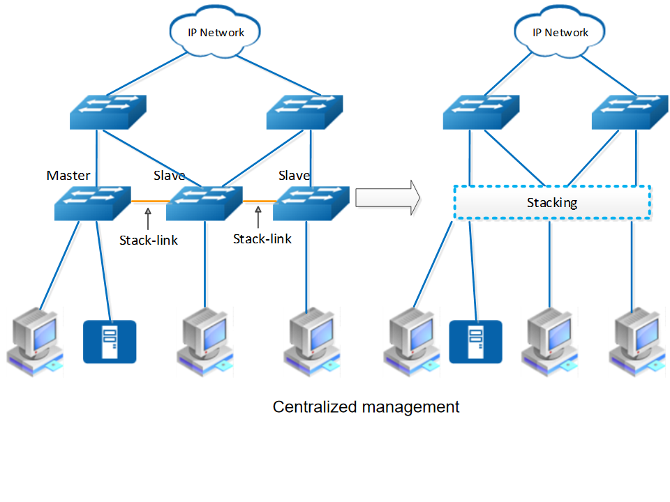
Stacking feature technology combines multiple physical switches into a single logical entity, enabling centralized management through unified configuration, enhanced reliability via cross-device redundancy with automatic failover, and flexible scalability through linear port/bandwidth expansion—all while maintaining synchronized forwarding tables (MAC/IP) and streamlined operations.
Key Benefits of Stacking:
✔ Cost-effective – No need for expensive chassis switches
✔ Highly available – Redundant architecture with fast failover
✔ Scalable – Expand ports/bandwidth by adding members
✔ Simplified management – Unified control plane for the entire stack
Ethernexion launched this stacking functionality in Q2 2025, now supported in the new E-NOS version V3.0.18 for both S5 and S7 series products.
Technical Background
Ethernet switches come in two form factors: box-style and chassis-style.
-
Box-style switches offer low cost but lack high availability and uninterrupted service protection, making them unsuitable for critical scenarios.
-
Chassis-style switches deliver high performance, high port density, and high availability, making them ideal for mission-critical deployments—but they come with high upfront costs and elevated per-port pricing.
Stacking technology bridges these two approaches by combining their advantages.
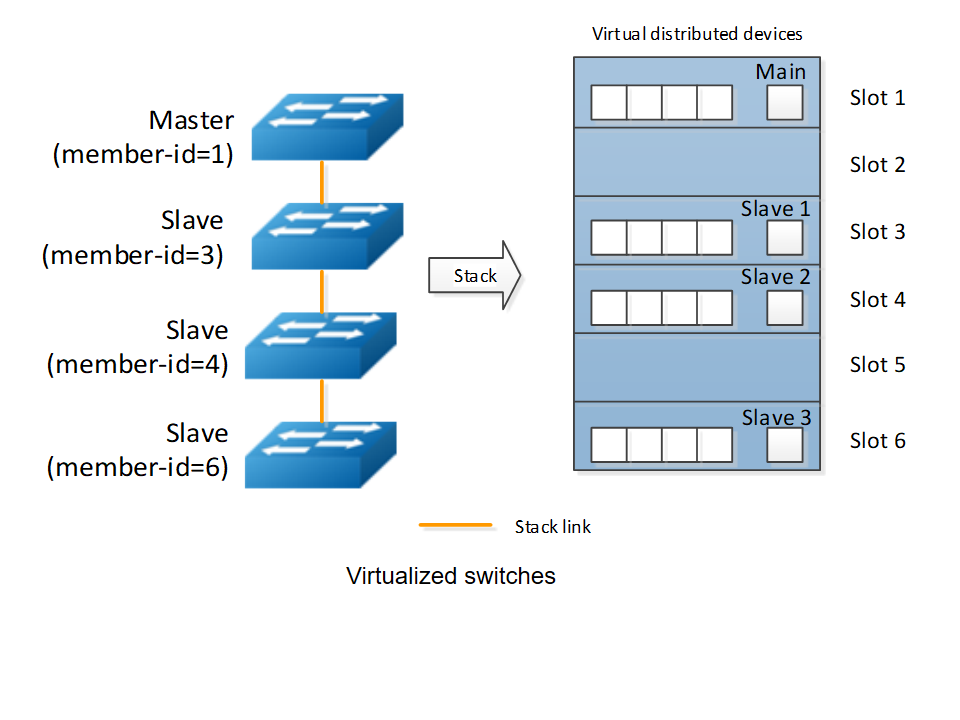
By connecting multiple devices through stacking ports, stacking creates a single virtual logical device. Managing this virtual device allows centralized control of all stack members. This hybrid solution retains the cost efficiency of box-style switches while delivering the scalability and high reliability of chassis-style distributed systems.
How to implement
Stacking Implementation Process
-
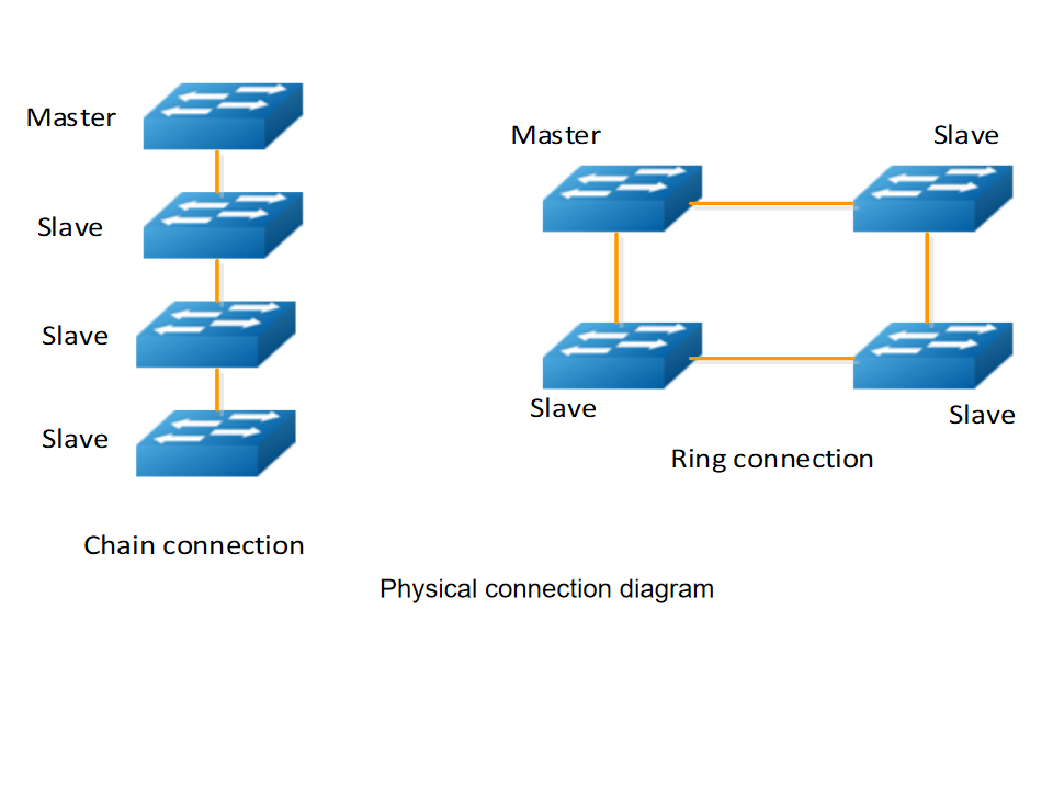
Physical Connection:
-
Member switches are interconnected via dedicated stacking ports using either:
-
Daisy-chain (linear) topology
-
Ring topology (recommended for higher reliability)
-
-
-
Role Assignment:
-
The system automatically elects one device as the Master (manages the entire stack) and others as Slaves (execute control-plane commands).
-
Role election is dynamic and adjusts upon topology changes (e.g., Master failure triggers re-election).
-
-
Data Forwarding:
-
Traffic flows through logical stacking links, with deterministic forwarding paths based on the topology.
-
Ring topologies enable bidirectional traffic for higher bandwidth utilization.
-
How to configure
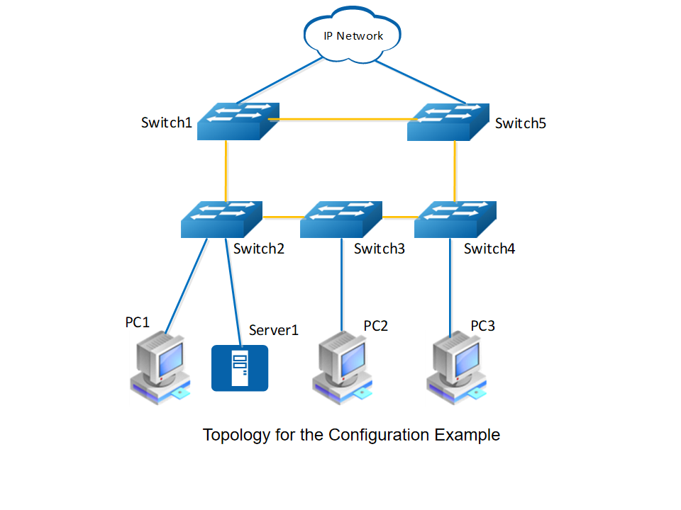
The following network example shows a ring stack system
-
Devices: Access switches Switch1-Switch5 form a 100G ring topology via uplink optical ports.
-
Purpose: Ensures high reliability for access-layer networks through stacking.
-
Stacking Roles:
-
Master: Switch1 (priority 200)
-
Backup Masters: Switch2 (190), Switch3 (180), Switch4 (170), Switch5 (160)
-
-
Stacking Ports:
eth-0-23toeth-0-26on each switch.
1. Initial Setup
# Enter configuration mode
Switch# configure terminal

# Enable stacking (requires reboot)
Switch(config)# stack enable
% Note: Configuration takes effect after saving and rebooting.
% Warning: Port configurations will be reset after stack enable/disable.
2. Member ID & Priority Configuration
# Configure slot ID and priority (reboot required)
Switch1(config)# stack slot 1 priority 200  # Master (highest priority)
Switch2(config)# stack slot 2 priority 190  # Backup Master
Switch3(config)# stack slot 3 priority 180  # Typo fixed from original
Switch4(config)# stack slot 4 priority 170
Switch5(config)# stack slot 5 priority 160
% All priority changes require 'write' and 'reboot' to activate.
3. Stacking Port Assignment
# Switch1 (Master):
Switch1(config)# interface stack-0-1
Switch1(config-if)# member-port eth-0-23
Switch1(config-if)# member-port eth-0-24  # Paired ports recommended
Switch1(config)# interface stack-0-5
Switch1(config-if)# member-port eth-0-25
Switch1(config-if)# member-port eth-0-26

# Switch2-Switch5: Follow same pattern with corresponding ports
% System reminder: "Add ports in pairs for redundancy!"
4. Save & Activate
# Exit and save
Switch(config-if)# end
Switch# write memory  # Save configuration
Switch# reload        # Reboot to apply stacking
5. Verification result
# Show topology (Ring structure visualized)
Switch(Master:1)# show stack topology
       M             S             S             S             S             M
    +-----+       +-----+       +-----+       +-----+       +-----+       +-----+
    |  1  |=======|  2  |=======|  3  |=======|  4  |=======|  5  |=======|  1  |
    +-----+       +-----+       +-----+       +-----+       +-----+       +-----+

# Check link status
Switch(Master:1)# show stack links
Stack-Port       Member-Ports        Status
============================================
stack-01-01      eth-01-23/24        UP
stack-01-05      eth-01-25/26        UP
... (abbreviated for clarity)